
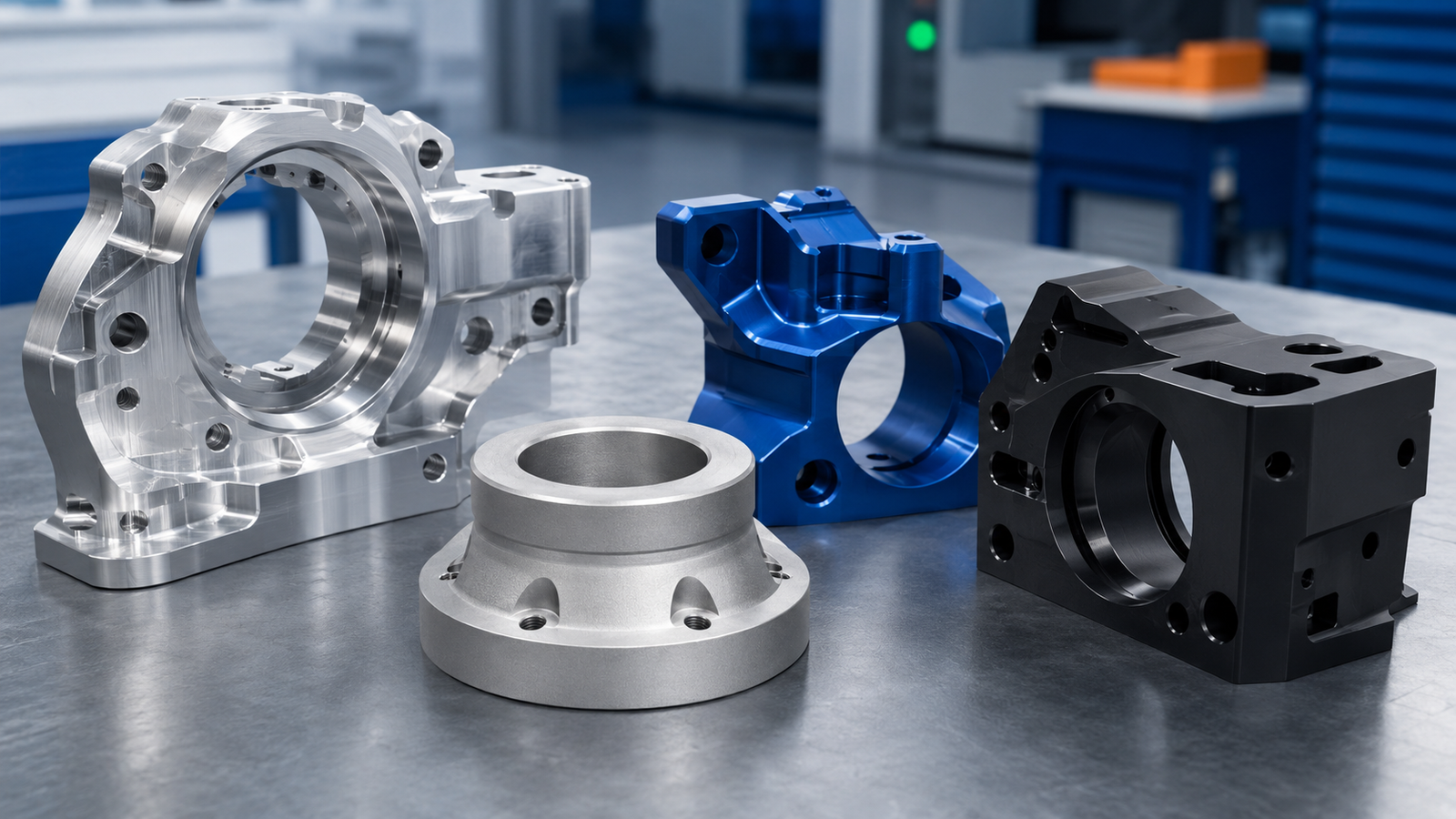
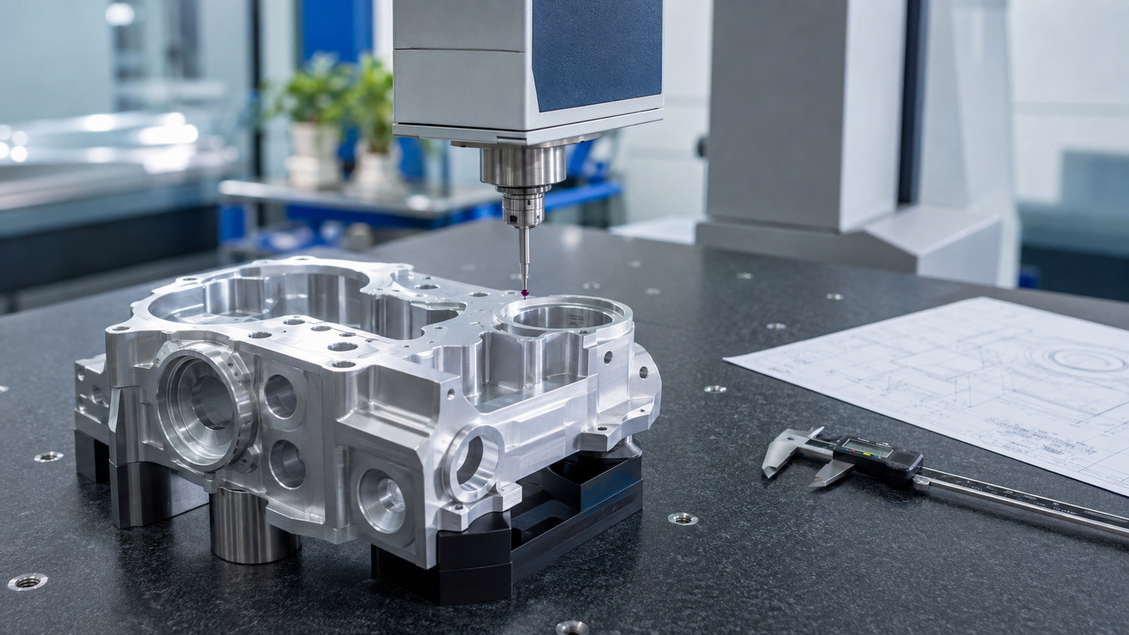
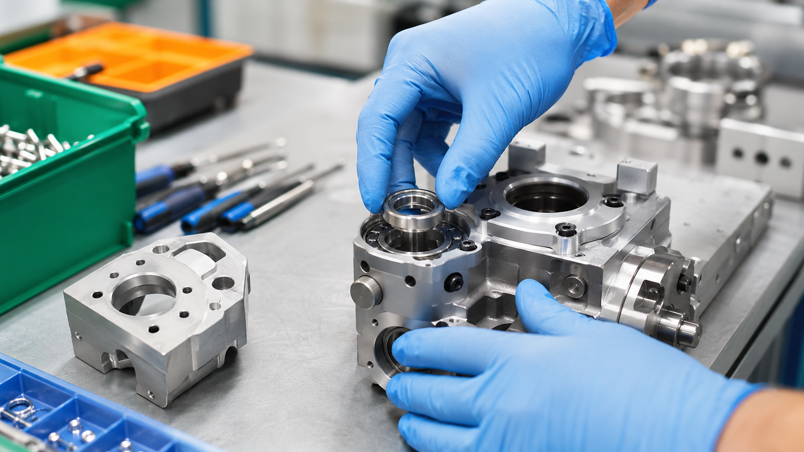
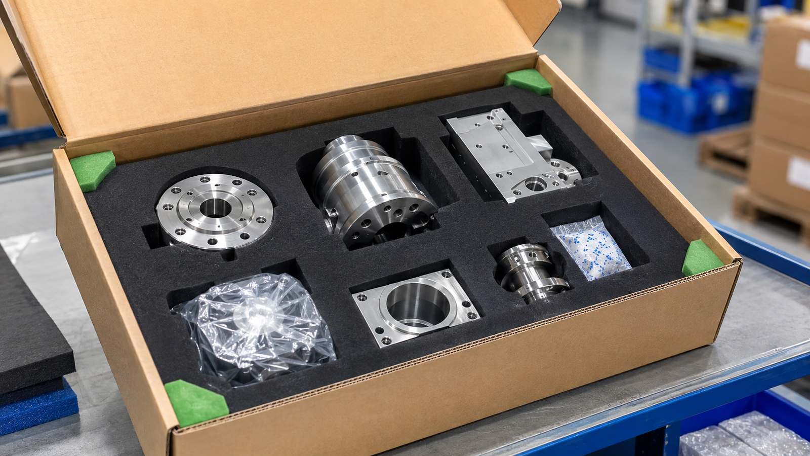




CNC milling and CNC turning are two of the most widely used processes for manufacturing precise metal and plastic components. Both methods use computer-controlled machines to remove material from a workpiece, but they differ significantly in how the workpiece moves, the cutting tools they use and the types of parts they produce most efficiently.
Understanding the differences between CNC milling and CNC turning helps engineers select the right process, improve manufacturability, reduce production costs and shorten lead times.
This guide explains how each process works, their main capabilities and how to decide which one is most suitable for your component.
What Is CNC Milling?
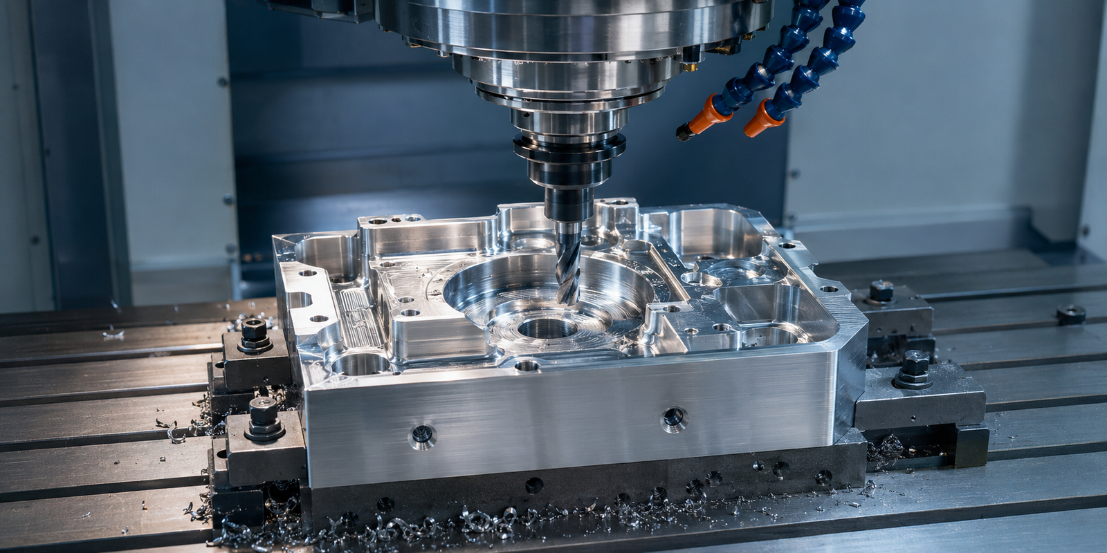
CNC milling is a subtractive manufacturing process in which a rotating cutting tool removes material from a stationary or controlled workpiece.
The workpiece is normally secured to the machine table using a vise, fixture, clamp or other workholding system. The cutting tool moves along multiple axes to create the required geometry.
A three-axis milling machine moves along the X, Y and Z axes. Four-axis and five-axis machines add rotational movement, allowing more faces and complex features to be machined with fewer setups.
Common CNC Milling Operations
CNC milling can perform operations such as:
- Face milling
- Pocket milling
- Slot milling
- Contouring
- Drilling and tapping
- Boring
- Chamfering
- Engraving
- Thread milling
- Surface profiling
Because the cutting tool can approach the workpiece from different directions, milling is particularly suitable for components containing flat surfaces, pockets, slots, hole patterns and irregular external profiles.
Typical CNC Milled Parts
Common CNC milled components include:
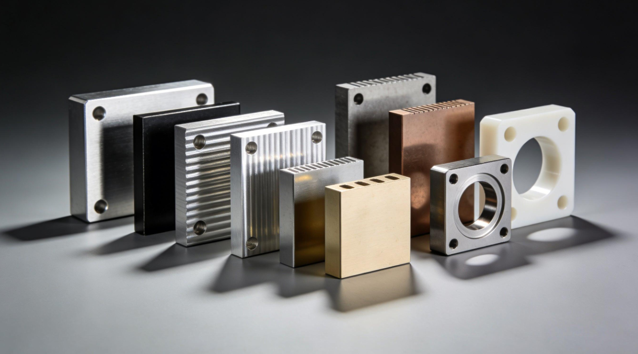
- Machine brackets
- Equipment housings
- Mounting plates
- Manifolds
- Mold inserts
- Jigs and fixtures
- Electronic enclosures
- Vacuum equipment components
- Automation components
- Prototype mechanical parts
What Is CNC Turning?
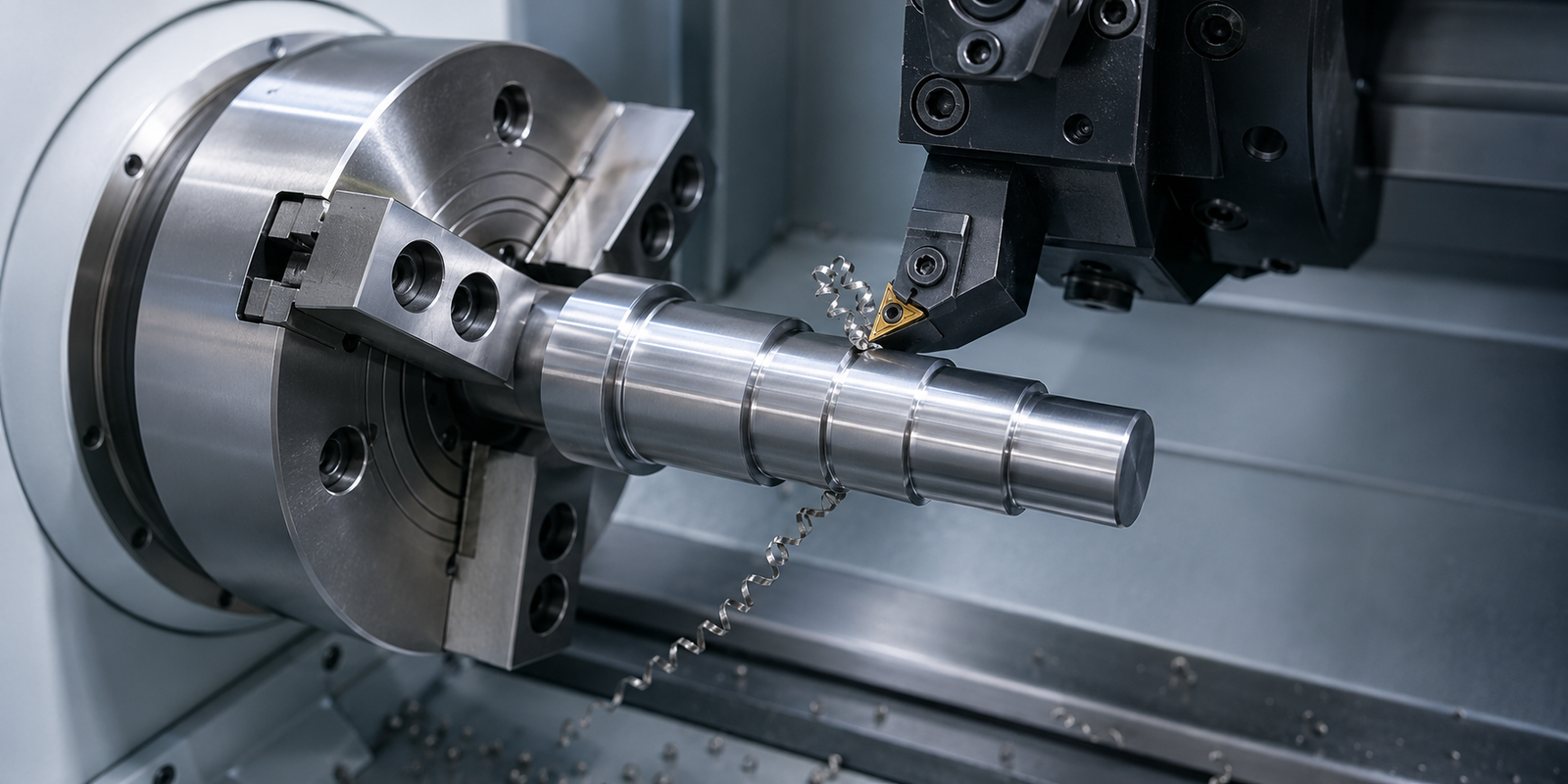
CNC turning is a subtractive manufacturing process in which the workpiece rotates while a stationary cutting tool removes material from its surface.
The raw material is usually round bar stock held in a chuck or collet. As the workpiece rotates, the cutting tool moves along its length and diameter to form the required profile.
CNC turning is especially efficient for producing cylindrical, conical and rotationally symmetrical components.
Common CNC Turning Operations
CNC turning can perform operations such as:
- Facing
- External turning
- Internal turning
- Grooving
- Parting
- Threading
- Drilling
- Boring
- Knurling
- Taper turning
Modern CNC lathes may also include live tooling, sub-spindles and additional axes. These capabilities allow certain milling, drilling and tapping operations to be completed without transferring the part to a separate machine.
Typical CNC Turned Parts
Common CNC turned components include:
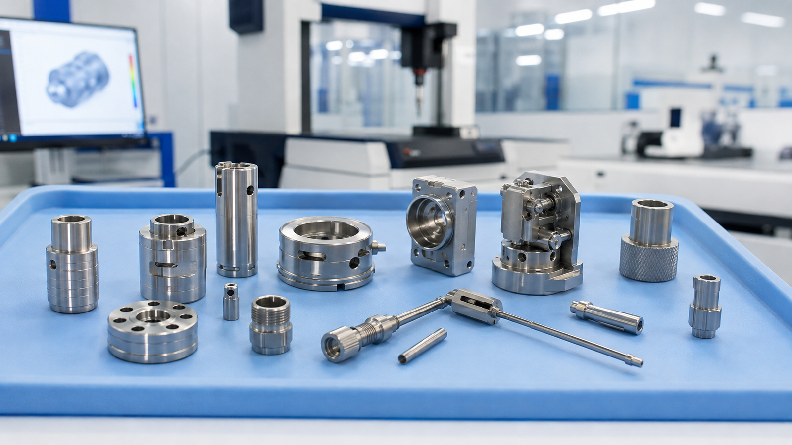
- Shafts
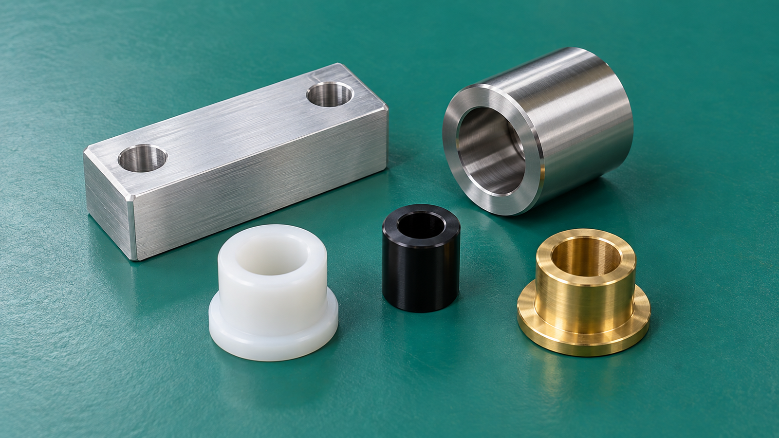
- Bushings
- Spacers
- Pins
- Rollers
- Sleeves
- Nozzles
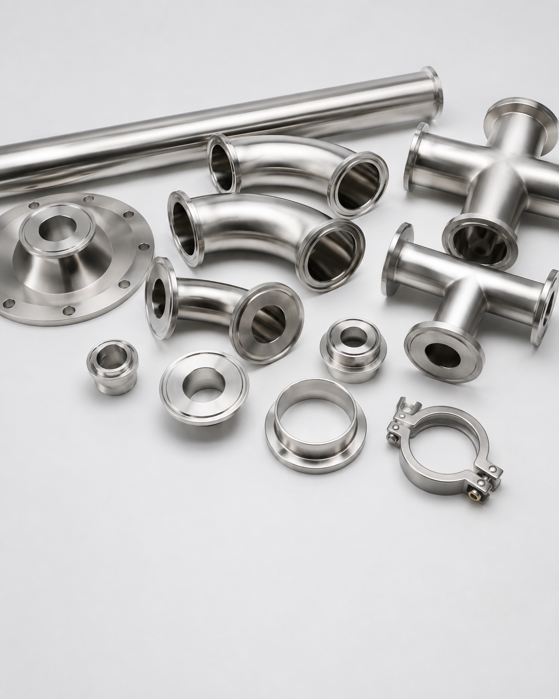
- Fittings
- Threaded connectors
- Flanges
- Bearing housings
- Vacuum adapters
CNC Milling vs. CNC Turning: Key Differences
The most important difference between CNC milling and CNC turning is the relative movement of the workpiece and cutting tool.
In CNC milling, the cutting tool rotates and moves around the workpiece. In CNC turning, the workpiece rotates while the cutting tool follows its profile.
| Comparison | CNC Milling | CNC Turning |
|---|---|---|
| Primary movement | Cutting tool rotates | Workpiece rotates |
| Most suitable geometry | Flat, prismatic and irregular parts | Cylindrical and rotational parts |
| Common raw material | Plates, blocks and castings | Round bars and tubes |
| Typical features | Pockets, slots, flat surfaces and hole patterns | Diameters, grooves, tapers and threads |
| Workholding | Vise, clamps or custom fixtures | Chuck, collet or soft jaws |
| Production efficiency | Efficient for multi-face components | Highly efficient for round components |
| Main accuracy strengths | Feature position, flat surfaces and profiles | Diameter, roundness and concentricity |
| Common machines | Three-axis, four-axis and five-axis mills | Two-axis lathes and mill-turn machines |
1. Part Geometry
Part geometry is usually the first factor to consider.
CNC milling is generally the better choice for components with:
- Rectangular or irregular shapes
- Multiple flat surfaces
- Deep or shallow pockets
- Slots and channels
- Hole patterns on different faces
- Three-dimensional contours
- Features that are not rotationally symmetrical
CNC turning is generally more suitable for components with:
- Round external profiles
- Stepped diameters
- Internal and external threads
- Concentric bores
- Grooves
- Tapers
- Cylindrical surfaces
- Rotational symmetry around a central axis
A simple way to identify the likely process is to imagine rotating the finished part around its centerline. If most of the geometry remains symmetrical during rotation, CNC turning will probably be the more efficient primary process.
2. Accuracy and Tolerances
Both CNC milling and CNC turning can achieve high dimensional accuracy when the process, machine, tooling and workholding are properly controlled.
CNC turning is particularly effective for controlling:
- Outside diameters
- Inside diameters
- Roundness
- Concentricity
- Runout
- Cylindrical fits
CNC milling is effective for controlling:
- Hole positions
- Center distances
- Flatness
- Perpendicularity
- Parallelism
- Pocket dimensions
- Profile dimensions
The achievable tolerance depends on more than the selected process. Part size, material, wall thickness, geometry, tool accessibility, heat generation and measurement method must also be considered.
Applying unnecessarily tight tolerances to every dimension can increase machining time, inspection requirements and production cost. Critical dimensions should therefore be identified clearly on the technical drawing.
3. Surface Finish
Both processes can produce high-quality machined surfaces, but their machining patterns are different.
Turned surfaces normally show fine concentric lines created by the rotation of the workpiece. Milled surfaces typically show linear or circular toolpaths depending on the cutting strategy.
Surface finish is affected by:
- Cutting speed
- Feed rate
- Tool geometry
- Tool condition
- Material properties
- Machine rigidity
- Workholding stability
- Coolant and chip evacuation
If a specific surface roughness is required, it should be stated on the drawing. Additional processes such as grinding, polishing, anodizing, passivation, plating or powder coating may be applied after machining.
4. Production Speed
CNC turning is often faster and more economical for rotationally symmetrical parts because many cylindrical features can be produced in one setup.
Bar-fed CNC lathes can also support efficient repeated production of small and medium-sized components.
CNC milling may require more tool changes, setups or workpiece repositioning, especially when features are located on multiple faces. However, four-axis and five-axis machines can reduce the number of setups required for complex parts.
Production speed depends on:
- Part complexity
- Quantity
- Raw material
- Number of setups
- Cutting tool access
- Tolerance requirements
- Inspection requirements
- Machine availability
Therefore, CNC turning is not automatically cheaper than milling, and milling is not automatically more expensive. The complete manufacturing process must be evaluated.
5. Tooling and Workholding
CNC milling commonly uses end mills, drills, reamers, taps, face mills and boring tools. The workpiece may be held in a standard vise or a dedicated fixture.
A custom fixture may be necessary when:
- The part has an irregular shape
- Multiple parts must be machined together
- Thin walls require additional support
- High repeatability is required
- Production quantities justify dedicated tooling
CNC turning commonly uses external turning tools, boring bars, grooving tools, threading tools and drills. Round stock is usually held in a chuck or collet.
Soft jaws may be machined to support delicate or finished surfaces and to improve concentricity during secondary operations.
6. Materials
Both CNC milling and CNC turning can process a wide range of metals and engineering plastics.
Common metals include:
- Aluminum
- Carbon steel
- Alloy steel
- Stainless steel
- Brass
- Copper
- Titanium
Common engineering plastics include:
- POM
- Nylon
- PEEK
- PTFE
- PMMA
- Bakelite
Material selection affects cutting parameters, tool wear, dimensional stability, surface finish and total cost.
For example, aluminum is generally easy to machine and suitable for prototypes, housings and lightweight components. Stainless steel offers higher corrosion resistance but normally requires more controlled cutting conditions. Engineering plastics may require special attention to clamping force, heat and deformation.
When Should You Choose CNC Milling?
Choose CNC milling when the component mainly contains:
- Flat or irregular geometry
- Pockets and slots
- Features on several faces
- Precise hole patterns
- Complex three-dimensional profiles
- Large plate or block-shaped raw material
Milling is also suitable when a prototype requires frequent design changes because programs and workholding can often be adapted without producing expensive permanent tooling.
When Should You Choose CNC Turning?
Choose CNC turning when the component mainly contains:
- Cylindrical geometry
- Stepped diameters
- Concentric bores
- Round grooves
- External or internal threads
- Shafts, sleeves, bushings or fittings
- Features arranged around a central axis
Turning is especially efficient when many identical round components must be produced from bar stock.
Can a Part Require Both Milling and Turning?
Yes. Many components contain both rotational features and non-rotational features.
For example, a shaft may require accurate turned diameters together with:
- Flat surfaces
- Cross holes
- Keyways
- Off-center holes
- Radial threaded holes
- Slots
These parts can be produced in several ways:
- Turn the primary cylindrical geometry on a CNC lathe and transfer the part to a milling machine.
- Mill a partially completed turned component in a dedicated fixture.
- Use a CNC lathe with live tooling.
- Use a mill-turn machining center to complete most features in one setup.
The most suitable approach depends on part complexity, tolerance relationships, production quantity and available equipment.
Using one setup can improve feature relationships and reduce handling, but advanced equipment may have a higher hourly cost. For some parts, using separate turning and milling operations remains the most economical solution.
Design Tips for CNC Milling
To improve the manufacturability of milled components:
- Add internal corner radii instead of specifying sharp internal corners.
- Avoid unnecessarily deep and narrow pockets.
- Provide adequate tool access.
- Maintain sufficient wall thickness.
- Use standard hole and thread sizes where possible.
- Avoid tight tolerances on non-critical dimensions.
- Consider how the component will be clamped.
- Reduce the number of required setups when practical.
Sharp internal corners cannot normally be produced with a standard rotating end mill. A suitable internal radius should therefore be included in the design.
Design Tips for CNC Turning
To improve the manufacturability of turned components:
- Use standard bar diameters when possible.
- Avoid very thin unsupported walls.
- Provide tool clearance near shoulders and grooves.
- Use standard thread forms and sizes.
- Avoid excessive length-to-diameter ratios.
- Specify realistic runout and concentricity requirements.
- Add suitable chamfers to edges and thread entries.
- Consider how the component will be held during secondary operations.
Long and slender parts may deflect or vibrate during machining. Additional support, reduced cutting forces or a revised machining sequence may be required.
How to Select the Right Process
Before selecting CNC milling or CNC turning, consider the following questions:
- Is the main geometry rotationally symmetrical?
- What raw material shape is most suitable?
- Which features carry the tightest tolerances?
- Are the critical dimensions related to the same setup?
- How many parts are required?
- Does the component need both turning and milling?
- Are any surfaces difficult for the cutting tool to reach?
- Are secondary finishing or inspection processes required?
The final decision should consider the complete manufacturing route rather than one individual feature.
A design may appear suitable for milling but become more economical when the main diameter is turned first. Similarly, a turned component with many off-center features may be more efficiently produced using mill-turn equipment or an additional milling setup.
CNC Milling and Turning at OSM Vietnam
OSM Vietnam supports custom CNC milling and CNC turning for prototypes, replacement parts and low-to-medium-volume production.
Our engineering review focuses on:
- Material selection
- Drawing requirements
- Critical tolerances
- Tool accessibility
- Workholding strategy
- Surface finish
- Inspection requirements
- Production quantity
- Delivery expectations
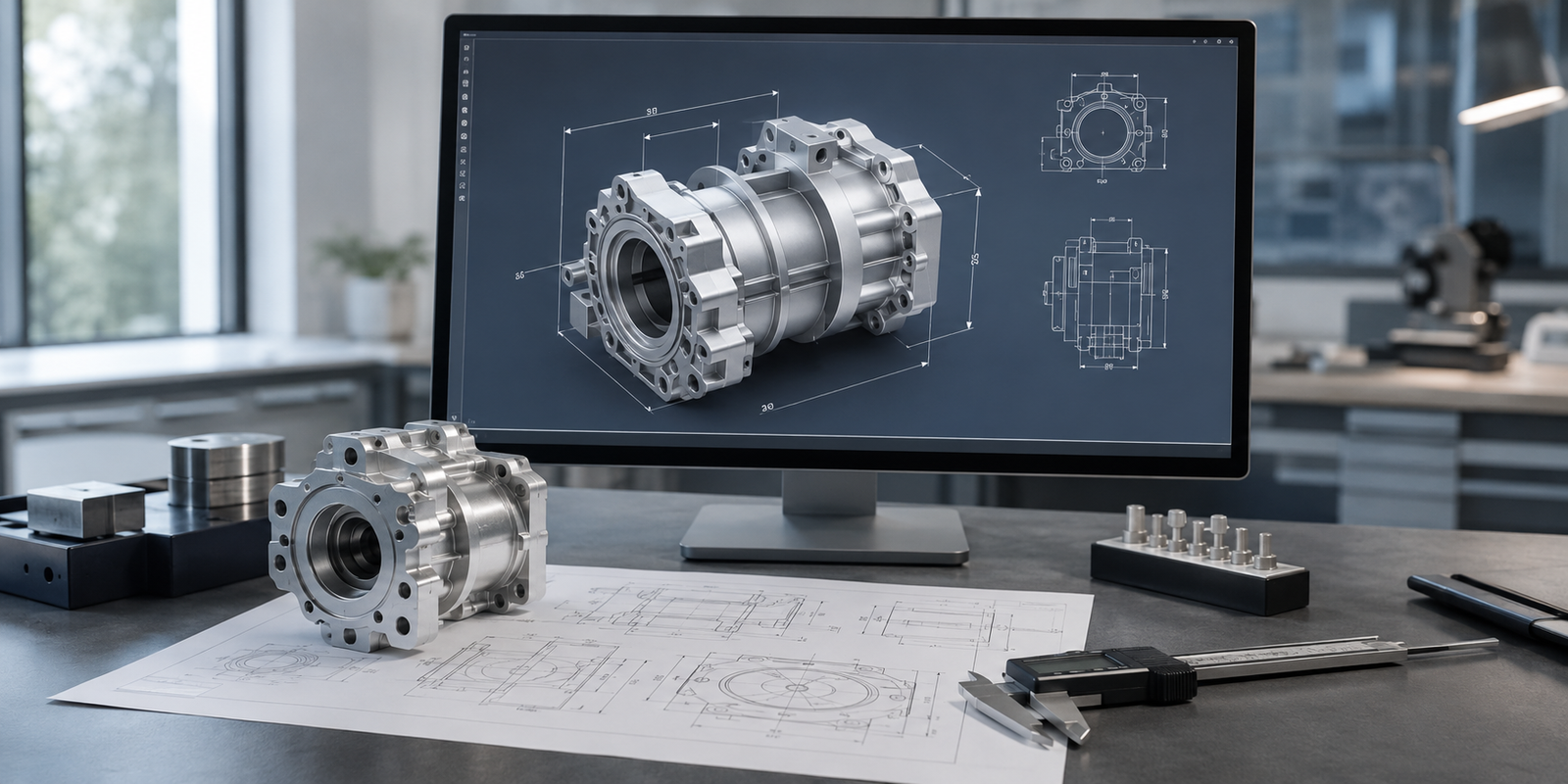
Before production, our engineers review the drawings and 3D models to identify potential manufacturing risks. If a feature may increase cost or affect stability, we can provide practical design-for-manufacturing recommendations.
Quality management processes at OSM Vietnam are aligned with ISO 9001 principles and are being developed toward future certification. Inspection requirements are confirmed according to the drawing and customer specifications.
Files Required for a Quotation
To prepare an accurate quotation, please provide:
- A 3D model in STEP, STP, IGES or a compatible format
- A 2D technical drawing in PDF or DWG format
- Material specification
- Required quantity
- Dimensional tolerances
- Surface finish requirements
- Heat treatment or coating requirements
- Inspection and documentation requirements
- Required delivery date
The 3D model defines the component geometry, while the 2D drawing identifies critical tolerances, threads, surface roughness and other requirements that may not be fully represented in the model.
Frequently Asked Questions
Is CNC milling more accurate than CNC turning?
Neither process is always more accurate. CNC turning is particularly effective for diameters, roundness, concentricity and runout. CNC milling is well suited to flatness, hole positions, profiles and features on multiple faces. Actual accuracy depends on the component design, machine, tooling, workholding and inspection method.
Is CNC turning cheaper than CNC milling?
Turning is often more economical for simple cylindrical components, especially when they can be produced efficiently from bar stock. However, cost depends on geometry, material, quantity, setup time, tolerances and secondary operations.
Can a CNC lathe produce holes and flat surfaces?
A basic CNC lathe can drill holes along the centerline. A lathe equipped with live tooling and additional axes may also produce cross holes, flat surfaces, slots and other milled features.
Can a rectangular component be CNC turned?
Turning is generally unsuitable as the primary process for rectangular components because the workpiece must rotate safely and predictably. Milling is normally the better option for rectangular or irregular parts.
Which process is better for prototypes?
Both processes are suitable for prototypes. The correct option depends mainly on part geometry. Round prototypes are commonly turned, while prismatic and irregular prototypes are normally milled.
Can OSM manufacture parts requiring both processes?
Yes. Components requiring both turning and milling can be produced through multiple coordinated setups or suitable combined machining methods. The production route is selected according to geometry, tolerances, quantity and cost.
Conclusion
The main difference between CNC milling and CNC turning is simple: CNC milling rotates the cutting tool around a controlled workpiece, while CNC turning rotates the workpiece against a cutting tool.
CNC milling is generally best for flat, prismatic and irregular components. CNC turning is generally best for cylindrical and rotationally symmetrical components. Parts containing both types of features may require a combination of the two processes.
Selecting the correct manufacturing method at the design stage can reduce setups, improve dimensional control, shorten lead times and lower production costs.
Need help selecting the right process for your component? Send your 3D model, technical drawing, material, quantity and inspection requirements to OSM Vietnam for an engineering review and quotation.