





Design for CNC Machining: 10 Practical Guidelines to Reduce Manufacturing Costs
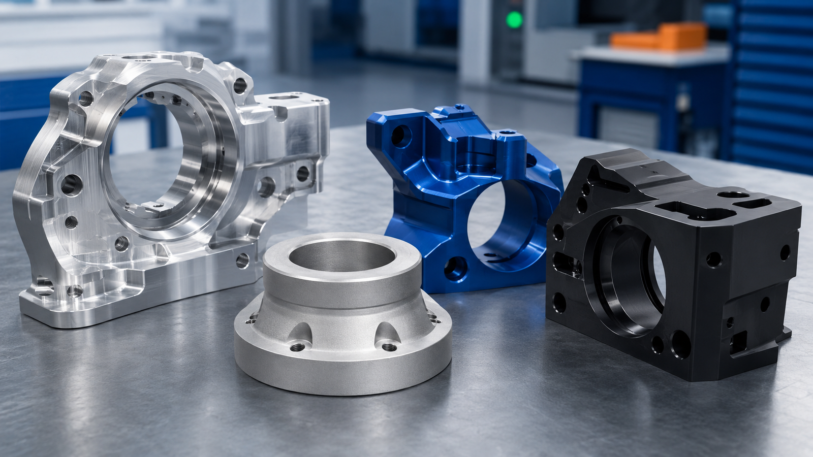
Design for CNC machining is not only about creating a part that meets functional requirements. A well-designed CNC component should also be practical to manufacture, easy to inspect, and cost-effective to produce.
Small design decisions—such as pocket depth, internal corner radius, wall thickness, or tolerance selection—can significantly influence machining time, tooling requirements, material waste, and overall production costs.
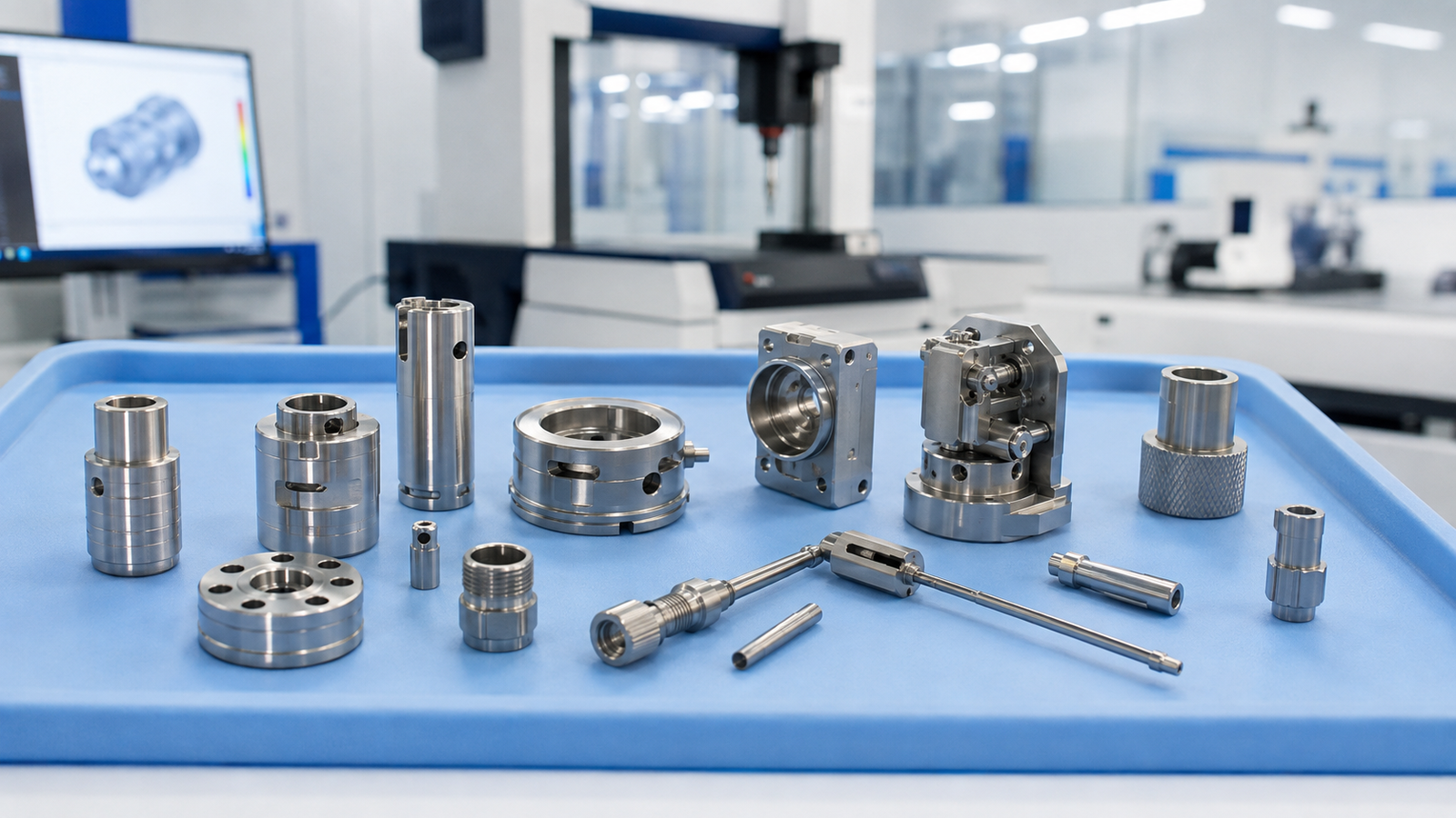
At OSM Vietnam, we support customers with practical design feedback and CNC machining solutions for custom mechanical components, from prototypes to production orders.
In this guide, we share 10 practical CNC machining design guidelines that can help engineers improve manufacturability without compromising essential part functions.
1. Avoid Unnecessarily Tight Tolerances
Tolerances are among the most important factors affecting CNC machining costs.
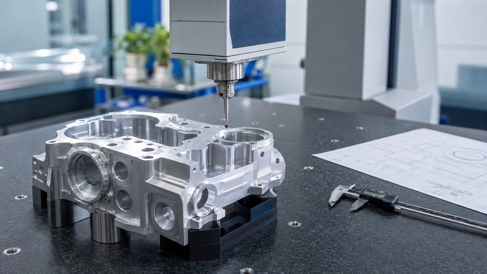
Tighter tolerances often require additional machining passes, careful setup, more frequent measurement, and longer inspection time.
For example, a non-critical dimension may work perfectly well with a general tolerance of ±0.1 mm, while a precision bearing fit or mating feature may require a much tighter tolerance.
Recommended approach:
- Apply tight tolerances only to dimensions that directly affect assembly, fit, or function.
- Use general tolerances for non-critical features where appropriate.
- Clearly identify critical dimensions on engineering drawings.
- Consider inspection requirements when specifying tolerances.
OSM supports general machining tolerances of approximately ±0.1 mm, with tighter tolerances down to ±0.01 mm on suitable critical features, depending on geometry, material, and inspection requirements.
Key takeaway: Use the tolerance required for functionality, not the tightest tolerance available.
2. Use Larger Internal Corner Radii
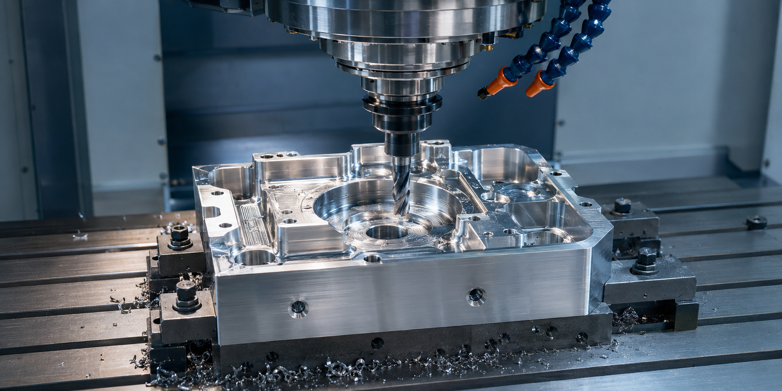
Sharp internal corners are difficult to manufacture using conventional CNC milling because rotating end mills naturally produce rounded internal corners.
A small internal radius requires a smaller cutting tool, which may reduce material removal rates and increase machining time.
When possible, design pockets with larger internal corner radii.
For deep pockets, a practical starting guideline is to use an internal radius of at least one-third of the pocket depth, where the part geometry allows.
Design recommendations:
- Avoid specifying sharp internal corners unless functionally necessary.
- Use larger corner radii whenever possible.
- Consider the relationship between pocket depth and cutter diameter.
- Discuss special corner requirements before finalizing the design.
Larger internal radii can allow the use of more rigid cutting tools and improve machining efficiency.
3. Avoid Excessively Deep Pockets
Deep pockets are common in aluminum housings, brackets, and other precision-machined components.
However, machining deep cavities may require long cutting tools, reduced cutting parameters, and additional finishing passes.
Long tool overhang can also increase vibration, tool deflection, and dimensional variation.
As a general design guideline, keep pocket depth within approximately four times the pocket width whenever practical.
For narrow or deep cavities, consider whether the same function can be achieved with a shallower pocket or a modified component design.
Benefits of shallower pockets:
- Shorter and more rigid cutting tools.
- Reduced machining time.
- Better dimensional consistency.
- Improved surface finish.
- Lower risk of tool vibration.
Deep pockets are still possible, but they should be reviewed carefully during the design stage.
4. Maintain Suitable Wall Thickness
Thin walls can be difficult to machine because cutting forces may cause vibration or deformation.
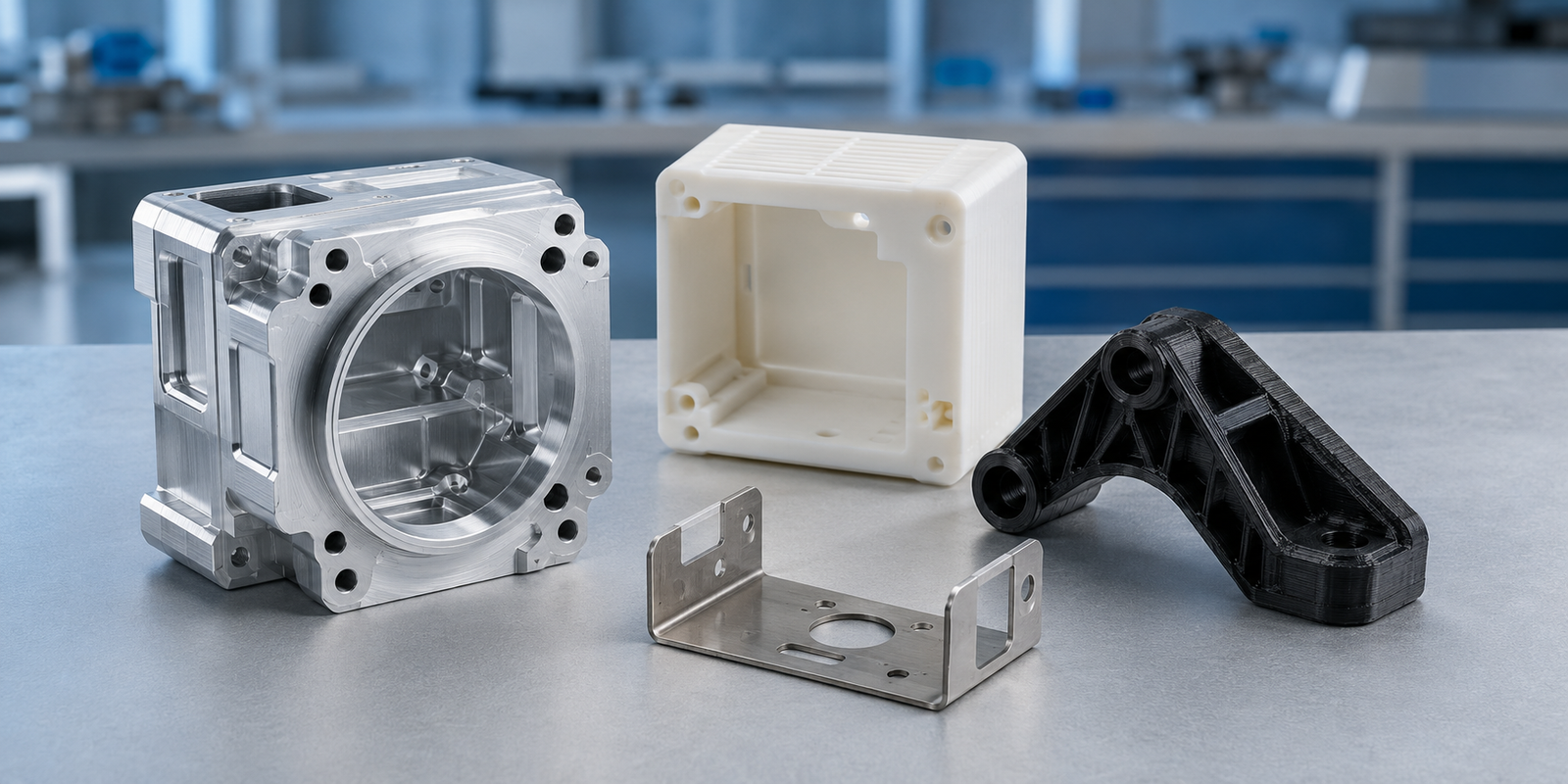
This is particularly important for aluminum housings, lightweight brackets, and engineering plastic components.
For preliminary design, OSM commonly recommends:
| Material | Suggested Minimum Wall Thickness |
|---|---|
| Metals | 0.8 mm |
| Engineering plastics | 1.5 mm |
These values are general design references rather than guaranteed minimum machining limits.
Actual manufacturability depends on wall height, geometry, material, clamping conditions, and required tolerances.
Where possible, use thicker walls to improve part rigidity and reduce manufacturing risks.
5. Design Holes with Standard Cutting Tools in Mind
Hole diameter, depth, and location can affect both machining cost and inspection requirements.
Standard hole sizes are generally easier to manufacture because suitable drilling tools are readily available.
Very small or deep holes may require specialized tooling, additional operations, or reduced cutting parameters.
Practical guidelines:
- Use standard drill diameters whenever possible.
- Avoid unnecessarily deep holes.
- For preliminary design, keep hole depth within approximately four times the diameter where practical.
- Provide sufficient clearance between holes and nearby walls.
- Specify hole tolerances only where needed for assembly or function.
For example, a clearance hole for a standard fastener usually does not require the same tolerance as a precision locating hole.
Selecting the correct hole requirements can simplify machining and reduce inspection time.
6. Optimize Threaded Hole Depth
Threaded holes are commonly used in mechanical assemblies, aluminum housings, and mounting brackets.
However, excessively deep threads may increase tapping time and create unnecessary manufacturing risks.
For initial design review, the following ranges can be considered:
| Thread Diameter | Preliminary Thread Depth Guideline |
|---|---|
| Ø1.5–5 mm | Up to approximately 3 × diameter |
| Ø5 mm and above | Approximately 4–6 × diameter, where justified |
These are preliminary machining considerations, not universal requirements for thread engagement.
The necessary engagement length must ultimately be determined by material strength, fastener grade, loading conditions, and the mechanical design.
Where possible, avoid specifying a full-depth thread when a shorter engagement length is sufficient.
7. Minimize the Number of Machining Setups
Every additional machining setup requires time for positioning, clamping, tool preparation, and verification.
Parts that can be machined from fewer orientations are generally easier to produce consistently.
For example, a component with most features accessible from one or two directions may be more economical than a similar part requiring machining from multiple sides.
Design recommendations:
- Group related features on accessible surfaces.
- Avoid unnecessary undercuts.
- Consider tool accessibility during the CAD design stage.
- Use consistent reference surfaces for important dimensions.
- Evaluate whether 4-axis machining could reduce repositioning.
Reducing the number of setups may improve positional accuracy and shorten production lead time.
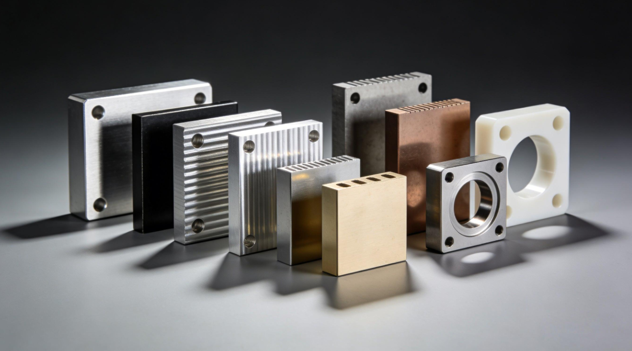
8. Choose Materials Based on Function and Machinability
Material selection affects not only product performance but also machining time, cutting tool wear, surface finishing, and raw material costs.
For example:
Aluminum 6061 is commonly selected for lightweight mechanical components because it offers good machinability and a useful balance of strength and corrosion resistance.
Stainless Steel 304 provides good corrosion resistance but generally requires more demanding machining conditions than aluminum.
Carbon Steel is suitable for many structural and mechanical components, with machinability varying by grade and condition.
POM is an engineering plastic commonly used for precision components requiring low friction and good dimensional stability.
When selecting materials, engineers should evaluate mechanical strength, operating environment, weight, availability, and total manufacturing cost.
A material that is unnecessarily expensive or difficult to machine may increase project costs without providing meaningful functional benefits.
9. Avoid Unnecessary Surface Finishing Requirements
Surface finishing can improve corrosion resistance, appearance, wear properties, or other functional characteristics.
However, not every CNC-machined part requires an additional surface treatment.
For internal components or parts operating in controlled environments, an as-machined finish may be sufficient.
Common finishing options include:
- As-machined finish.
- Anodizing for aluminum.
- Electroplating.
- Black oxide.
- Powder coating.
- Polishing.
- Sandblasting.
Select the finishing process based on actual performance requirements.
For example, an aluminum component requiring additional corrosion protection may benefit from anodizing, while a non-visible prototype may not require a decorative finish.
Avoid specifying cosmetic requirements for surfaces where appearance does not affect functionality.
10. Prepare Complete CAD Files and Engineering Drawings
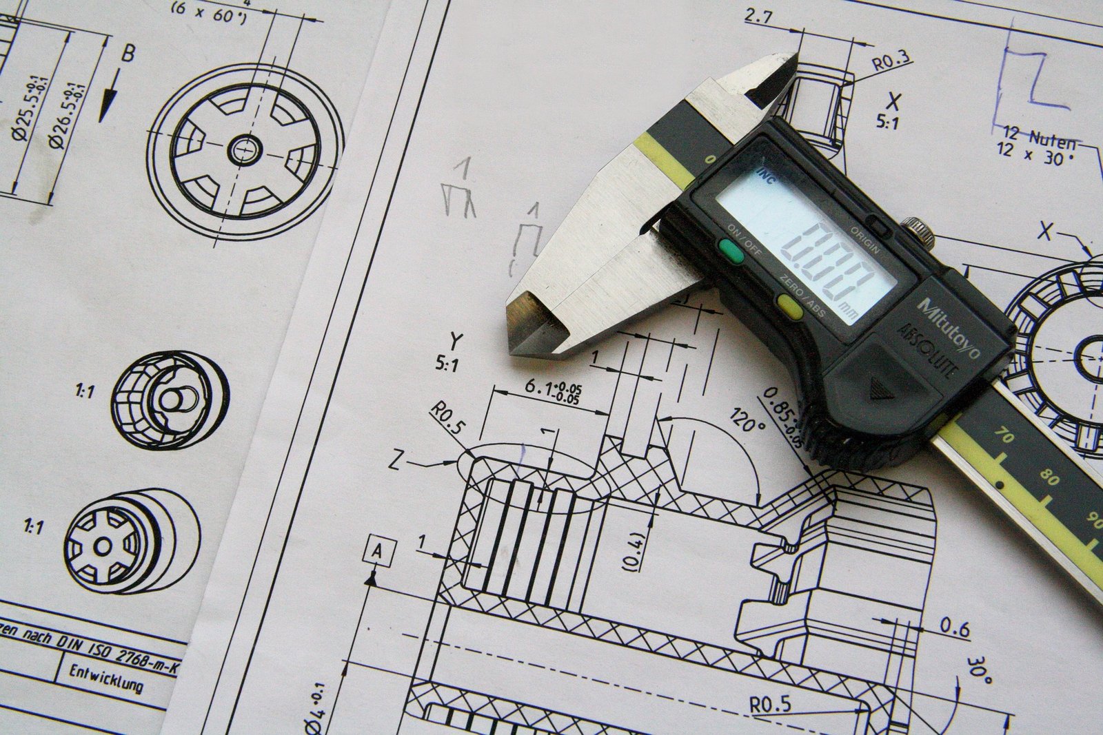
Clear manufacturing documentation is essential for accurate quotation and efficient production.
Incomplete drawings or missing specifications may lead to additional clarification, quotation delays, or manufacturing errors.
When requesting a CNC machining quotation, prepare the following information whenever available:
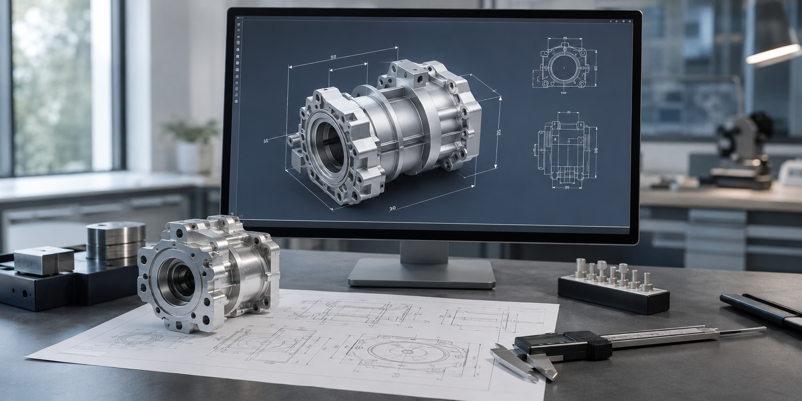
- 3D CAD model: STEP or another compatible solid-model format.
- 2D engineering drawing: PDF with critical dimensions and tolerances.
- Material specification: Required grade or acceptable alternatives.
- Surface finish: As-machined or specified treatment.
- Quantity: Prototype quantity or expected production volume.
- Critical features: Fits, threads, inspection requirements, and assembly interfaces.
- Delivery requirements: Requested lead time and destination.
A complete RFQ package helps the machining supplier understand the project and provide a more reliable quotation.
How Design for Manufacturability Helps Reduce CNC Machining Costs
Design for Manufacturability (DFM) is the process of reviewing a component design to identify opportunities for more efficient and reliable production.
A practical DFM review may consider:
| Design Factor | Potential Manufacturing Benefit |
|---|---|
| Appropriate tolerances | Less unnecessary precision machining and inspection |
| Larger internal radii | More efficient milling with suitable cutting tools |
| Shallower pockets | Reduced tool overhang and machining time |
| Suitable wall thickness | Improved rigidity and reduced deformation risk |
| Standard hole sizes | Simpler tooling and drilling operations |
| Fewer machining setups | Reduced setup time and improved consistency |
| Appropriate material selection | Better balance of performance and manufacturing cost |
| Clear technical drawings | Fewer quotation delays and production misunderstandings |
Not every recommendation will apply to every component. The best solution depends on the function, geometry, material, and production requirements.
CNC Design Support from OSM Vietnam
OSM Vietnam is a precision CNC machining workshop supporting international customers with custom mechanical parts.
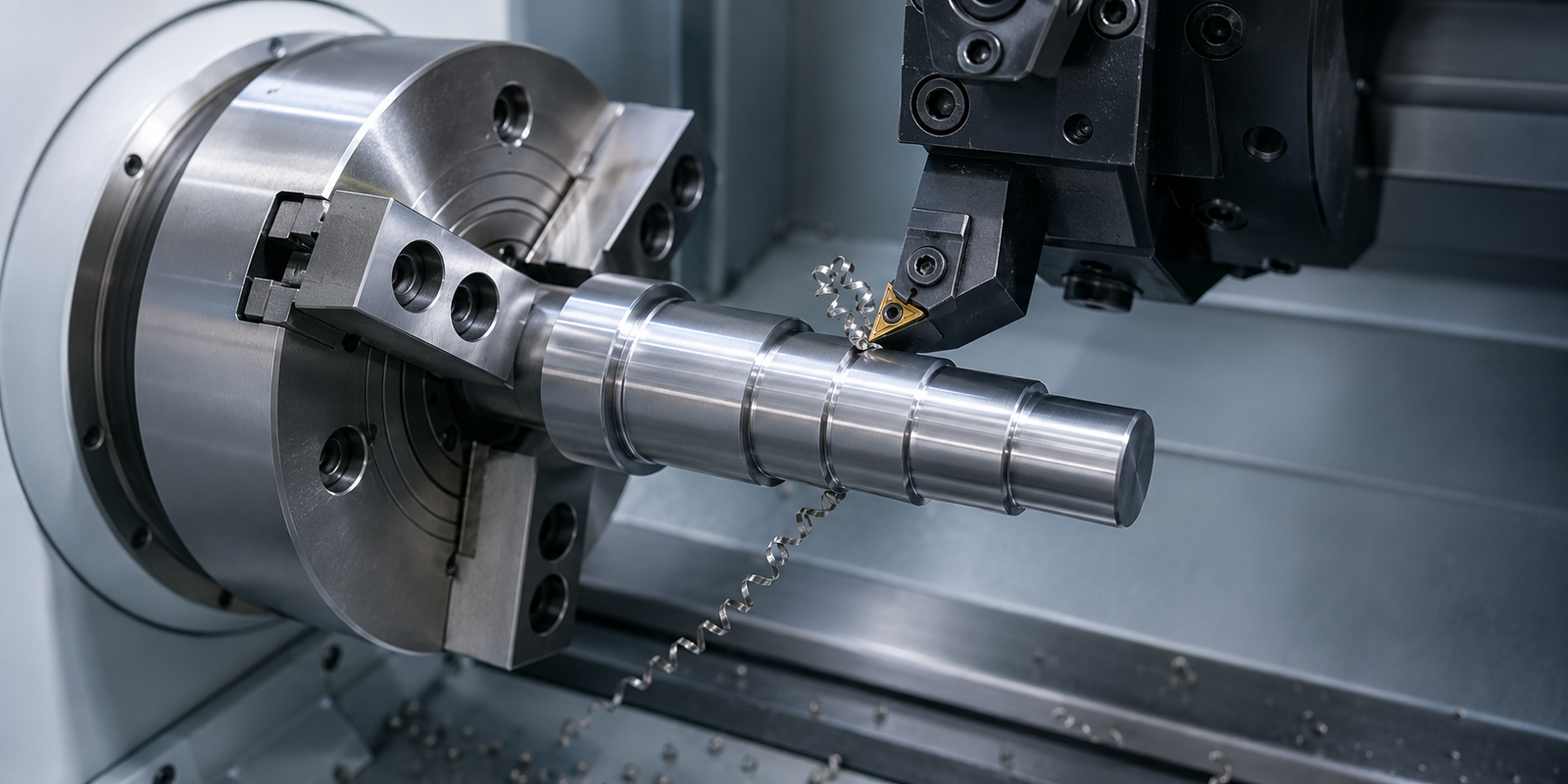
Our services include CNC milling, CNC turning, rapid prototyping, and manufacturing-related engineering support.
When customers provide CAD models and technical drawings, our team can review important manufacturing considerations, discuss potential design improvements, and recommend practical machining approaches.
We focus on clear technical communication, consistent quality, and manufacturing solutions suitable for each project.
Whether you are developing a new prototype or preparing a production order, early communication between the design team and machining supplier can help reduce unnecessary costs and avoid preventable manufacturing problems.
Frequently Asked Questions
What is design for CNC machining?
Design for CNC machining is the practice of creating mechanical components with consideration for machining capabilities, cutting tool access, material selection, tolerances, and production costs.
How can I reduce CNC machining costs?
Common approaches include avoiding unnecessarily tight tolerances, simplifying part geometry, using standard hole sizes, reducing deep pockets, selecting suitable materials, and minimizing machining setups.
What is the recommended minimum wall thickness for CNC machining?
For preliminary design, OSM commonly recommends approximately 0.8 mm for metals and 1.5 mm for engineering plastics. Actual requirements depend on geometry, material, and machining conditions.
Do I need both 2D drawings and 3D CAD files?
A 3D CAD model helps define part geometry, while a 2D drawing communicates critical tolerances, materials, surface finishes, and inspection requirements. Providing both is recommended for accurate quotation and manufacturing.
Can OSM review my design before manufacturing?
Yes. OSM can review customer drawings and CAD models and provide practical manufacturing feedback based on the project’s requirements and available machining capabilities.
Conclusion
Good design for CNC machining balances functional performance, manufacturing feasibility, dimensional accuracy, and cost.
By applying practical design guidelines early in product development, engineers can simplify machining operations, improve production consistency, and reduce unnecessary manufacturing expenses.
Looking for a CNC machining partner in Vietnam?
Send your CAD files and engineering drawings to OSM Vietnam for technical review and a customized machining quotation.
Request a Quote: https://osmviet.com/cnc-machining-services-in-vietnam/