








CNC Milling Design Guidelines: Wall Thickness, Holes, Pockets and Internal Radii
CNC milling design guidelines help engineers create mechanical parts that are easier to manufacture, inspect, and assemble. Good design decisions can reduce machining time, improve dimensional consistency, and avoid unnecessary manufacturing costs.
Features such as thin walls, deep pockets, small internal radii, and difficult-to-access holes can significantly affect the CNC milling process.
At OSM Vietnam, we manufacture custom CNC-milled components for prototypes and production orders. Our team also supports customers with practical design feedback based on part geometry, material selection, and machining requirements.
This guide explains the main design considerations for CNC milling, with a focus on wall thickness, holes, pocket depth, and internal corner radii.
1. Why CNC Milling Design Guidelines Matter
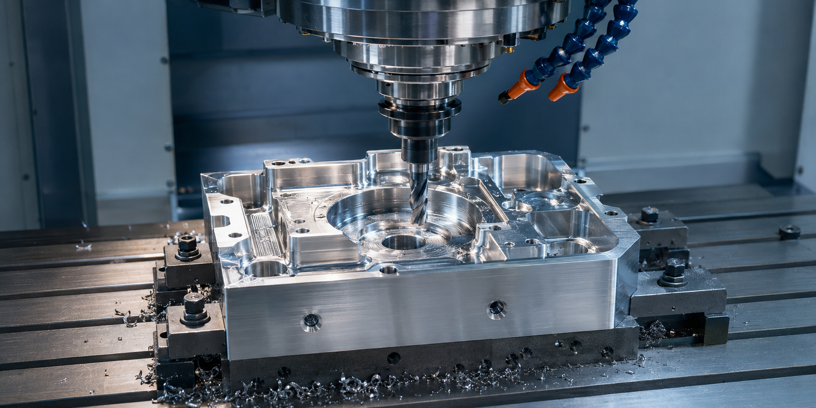
CNC milling removes material from a solid workpiece using rotating cutting tools. The cutting tools must have sufficient access to the features being machined, while the workpiece must remain stable during the process.
A design that looks simple in a CAD model may require complex tooling, additional setups, or slower machining parameters.
Common design-related manufacturing challenges include:
- Thin walls that vibrate or deform during cutting.
- Deep pockets that require long cutting tools.
- Small internal radii that limit tool diameter.
- Deep or narrow holes that require specialized drilling methods.
- Features that are difficult to clamp or access.
- Tight tolerances applied to non-critical dimensions.
Considering these factors early can help improve manufacturability before the drawing is released for quotation.
2. Minimum Wall Thickness for CNC Milling
Wall thickness affects the rigidity and dimensional stability of a CNC-machined part.
Thin walls may bend under cutting forces, especially when the wall is tall, unsupported, or made from a relatively flexible material.
For preliminary design, OSM commonly uses the following reference values:
| Material | Suggested Minimum Wall Thickness |
|---|---|
| Metals | 0.8 mm |
| Engineering plastics | 1.5 mm |
These are general design recommendations, not guaranteed machining limits.
Actual requirements depend on material properties, wall height, length, clamping conditions, and dimensional tolerances.
Design Recommendations for Thin Walls
- Use thicker walls where the product design allows.
- Avoid long, unsupported walls.
- Add ribs or supporting features when necessary.
- Consider machining forces and possible deformation.
- Review thin-wall features with the machining supplier before production.
For example, an aluminum housing with a tall, thin outer wall may require careful machining and additional support to maintain dimensional accuracy.
Design tip: Wall height and unsupported length are often just as important as wall thickness.
3. CNC Milling Pocket Design
Pockets are recessed features commonly found in aluminum housings, mounting blocks, brackets, and mechanical components.
Pocket geometry influences cutting tool selection, machining time, and achievable surface finish.
Recommended Pocket Depth
As an initial design guideline, keep pocket depth within approximately four times the pocket width whenever practical.
Deep pockets often require longer cutting tools, which may increase vibration and tool deflection.
The achievable depth also depends on the cutter diameter, toolholder clearance, material, and pocket geometry.
How to Improve Pocket Design
- Avoid unnecessarily deep cavities.
- Increase pocket width where possible.
- Provide adequate clearance for cutting tools.
- Use larger internal corner radii.
- Consider whether the pocket can be accessed from another side.
- Avoid narrow, deep features that require very small tools.
Example: Shallow vs. Deep Pocket
Consider two aluminum parts with similar overall dimensions.
Design A: A relatively shallow pocket with open tool access.
Design B: A narrow pocket with significantly greater depth.
Design B may require a longer end mill, reduced cutting parameters, and additional finishing passes.
If both designs perform the same function, Design A may offer a more economical machining solution.
4. Internal Corner Radius in CNC Milling
Internal corner radii are important because conventional CNC milling tools are cylindrical.
When an end mill machines the inside corner of a pocket, it naturally leaves a rounded corner.
Producing a very small radius generally requires a smaller cutter.
Smaller cutters may reduce machining efficiency, particularly in deep pockets.
Recommended Internal Radius
For preliminary design, an internal radius of at least one-third of the pocket depth can be considered where geometry permits.
This is a conservative design preference rather than a universal machining requirement.
The actual radius should be selected based on pocket depth, tool diameter, accessibility, and functional requirements.
Practical Design Recommendations
- Use the largest internal radius permitted by the design.
- Avoid sharp internal corners unless functionally necessary.
- Keep corner radii consistent when possible.
- Consider cutter access in deep pockets.
- Discuss alternative corner-relief designs if a mating component requires a sharp external corner.
Why Larger Radii Can Reduce Costs
A larger internal radius may allow the use of a larger, more rigid end mill.
This can improve material removal efficiency, reduce tool deflection, and support more consistent machining results.
However, the best radius depends on the overall geometry and manufacturing process.
5. CNC Hole Design Guidelines
Holes are among the most common features in CNC-milled parts.
They may be used for fasteners, locating pins, shafts, fluid passages, or assembly interfaces.
Hole diameter, depth, tolerance, and position all influence manufacturability.
Minimum Hole Diameter
OSM uses a general preliminary design reference of 1.0 mm minimum hole diameter for conventional machining.
Smaller holes may be possible with suitable tools and processes, but they require individual evaluation.
Recommended Hole Depth
For standard drilling applications, a hole depth of up to approximately four times the diameter is a useful initial guideline.
Deeper holes can still be manufactured, but may require specialized drilling tools, different machining strategies, or additional process control.
Hole Design Recommendations
- Prefer standard drill diameters.
- Avoid unnecessary deep holes.
- Allow adequate distance between holes and thin walls.
- Specify hole tolerances according to assembly requirements.
- Clearly identify precision locating holes.
- Consider tool access and drilling direction.
A simple clearance hole normally does not need the same dimensional tolerance as a precision dowel-pin hole.
6. Threaded Hole Design for CNC-Milled Parts
Threaded holes are widely used in brackets, housings, mounting plates, and mechanical assemblies.
Thread size, depth, and material must be considered together.
Excessive thread depth may increase machining time without improving the joint.
Thread Design Considerations
- Use standard thread sizes where possible.
- Provide adequate space for tapping tools.
- Avoid unnecessary thread depth.
- Specify blind-hole depth and usable thread length clearly.
- Consider material strength and fastener loading.
- Review small or deep threads before manufacturing.
For preliminary machining review, OSM’s design reference includes thread depths up to approximately three times the diameter for small threads and potentially deeper features for larger threads when required.
These values describe machining considerations, not required thread engagement lengths.
Important: The actual engagement length must be determined from joint strength, loading, fastener specification, and material properties.
7. Slots and Narrow Features
Slots are commonly used for adjustment, mounting, alignment, and mechanical movement.
However, narrow and deep slots may require small cutting tools and longer machining cycles.
A slot with a high depth-to-width ratio can be particularly challenging because of tool rigidity and chip evacuation.
Recommended Slot Design
- Avoid very narrow, deep slots when possible.
- Increase slot width if the design permits.
- Provide adequate end radii.
- Consider tool diameter and accessibility.
- Avoid unnecessary precision requirements on non-critical slots.
For simple preliminary design, OSM uses minimum slot-width references of approximately 0.8 mm for metals and 1.0 mm for plastics, subject to part geometry and machining feasibility.
These values should be confirmed during technical review.
8. Designing for 3-Axis and 4-Axis CNC Milling
The number of machine axes can influence how a component should be designed.
3-Axis CNC Milling
Three-axis CNC milling is commonly used for parts with accessible planar surfaces, pockets, holes, and standard prismatic features.
Typical applications include:
- Mounting plates.
- Aluminum brackets.
- Machine blocks.
- Simple housings.
- Fixtures and mechanical supports.
4-Axis CNC Milling
Four-axis CNC milling adds rotational positioning or motion, allowing machining from multiple orientations with fewer manual repositioning operations in suitable applications.
It can be useful for:
- Features distributed around a cylindrical component.
- Parts requiring machining on multiple sides.
- Certain curved or angular features.
- Components where reducing setups improves positional consistency.
Not every complex part requires 4-axis machining. The most appropriate method depends on geometry, quantity, tolerances, and available equipment.
9. Consider Machining Setup and Workholding
A CNC part must be securely held during machining.
Features that are difficult to clamp may require special fixtures, additional setup time, or changes to the machining sequence.
Designers should consider whether the component has suitable reference surfaces and enough accessible material for stable workholding.
Practical Workholding Guidelines
- Provide stable surfaces for clamping where possible.
- Avoid placing critical features in areas that are difficult to access.
- Minimize unnecessary machining orientations.
- Consider how the part will be held during finishing operations.
- Identify important datum surfaces on the engineering drawing.
For repeated production, suitable workholding can help improve consistency and reduce setup variation.
10. Use Appropriate Tolerances and Surface Finishes
Even when a part is easy to machine geometrically, excessive tolerances or surface requirements may increase production costs.
A general tolerance may be sufficient for non-critical features, while precision fits require closer control.
At OSM, general CNC milling tolerances are typically around ±0.1 mm, while suitable critical features may be manufactured to tighter tolerances down to ±0.01 mm, depending on technical requirements.
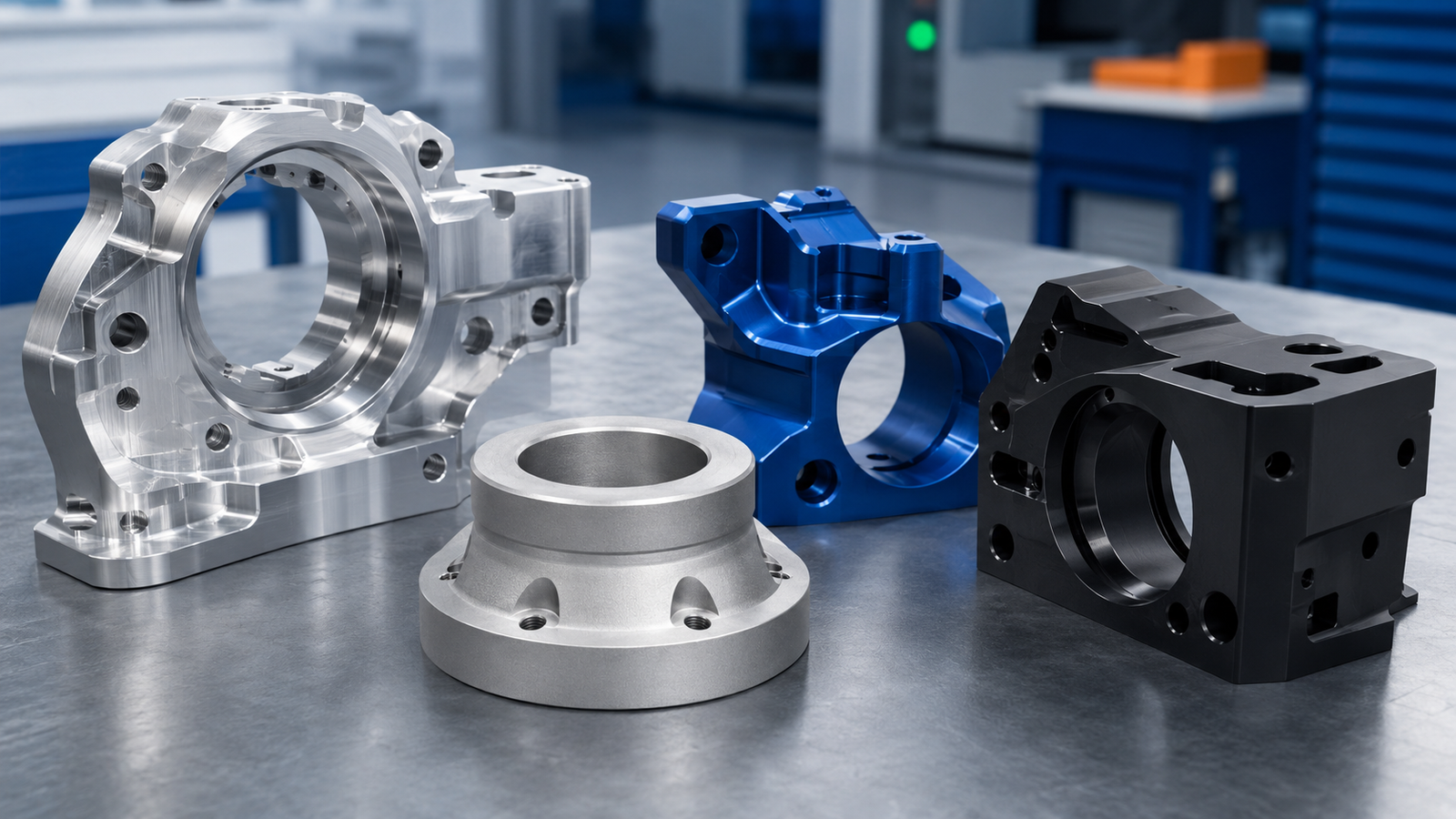
Surface finish should also be selected according to the part’s function.
Common options include:
- As-machined.
- Anodizing.
- Black oxide.
- Electroplating.
- Powder coating.
- Polishing.
- Sandblasting.
Avoid specifying unnecessary cosmetic or dimensional requirements on surfaces where they do not affect the product’s performance.
11. CNC Milling Design Checklist
Before sending a CNC milling drawing for quotation, review the following items:
| Design Item | What to Check |
|---|---|
| Wall thickness | Is the wall sufficiently rigid for machining? |
| Pocket depth | Can the pocket be reached with suitable cutting tools? |
| Internal radii | Are corner radii large enough for efficient milling? |
| Holes | Are diameters and depths practical? |
| Threads | Are thread sizes and usable depths clearly specified? |
| Slots | Are narrow or deep slots necessary? |
| Tolerances | Are tight tolerances limited to functional features? |
| Surface finish | Is each finishing requirement justified? |
| Workholding | Can the part be clamped securely? |
| Documentation | Are CAD files, drawings, materials, and quantities complete? |
A short design review before quotation can help prevent avoidable manufacturing problems.
12. CNC Milling Design Support from OSM Vietnam
OSM Vietnam is a precision CNC machining workshop providing custom machining services for international customers.
Our capabilities include 3-axis and 4-axis CNC milling, CNC turning, rapid prototyping, and technical support for custom mechanical parts.
We work with common engineering materials such as aluminum, carbon steel, stainless steel, brass, copper, and engineering plastics.
Customers can submit their CAD models and engineering drawings for manufacturing review and quotation.
Our team can discuss practical design considerations, material options, machining approaches, and inspection requirements before production.
We focus on supporting customers who value clear communication, technical collaboration, and reliable manufacturing services.
Frequently Asked Questions
What is the minimum wall thickness for CNC milling?
As a preliminary guideline, OSM recommends approximately 0.8 mm for metals and 1.5 mm for engineering plastics. The actual minimum depends on geometry, material, and machining conditions.
What is a suitable internal corner radius for CNC milling?
Larger internal radii are generally easier to machine. For preliminary design, a radius of at least one-third of the pocket depth can be considered where the geometry permits, but the final choice depends on tool access and functional requirements.
How deep can a CNC-milled pocket be?
Pocket depth depends on width, cutting tool diameter, material, and tool accessibility. Keeping pocket depth within approximately four times its width is a useful preliminary guideline, although deeper pockets may be possible.
What is the minimum hole diameter for CNC milling?
A diameter of approximately 1.0 mm is a practical starting reference for conventional CNC machining at OSM. Smaller holes require individual technical evaluation.
Can OSM review my CNC milling design before production?
Yes. OSM can review CAD models and technical drawings and provide practical feedback on manufacturability, material selection, machining methods, and inspection requirements.
Conclusion
Following practical CNC milling design guidelines can help engineers improve manufacturability, reduce unnecessary machining operations, and achieve more consistent production results.
Wall thickness, pocket geometry, internal corner radii, hole design, and workholding should all be considered before finalizing a CNC-milled component.
Need CNC milling support in Vietnam?
OSM Vietnam can review your drawings and provide a quotation for custom CNC-milled components, from prototypes to production orders.
Request a Quote: https://osmviet.com/cnc-machining-services-in-vietnam/